[프로젝트] Vision based Automous Human Following Wheeled Mobile Robot
Inha univ, Alpha project
[code]
Author: Jongha Kim
Reviews
이번 프로젝트는 Vision 기반의 자율 주행 로봇을 개발하는 것으로, 사람을 인식하고 따라가는 기능을 구현하는 것이 주요 목표였습니다. 주어진 플랫폼은 TurtleBot3 Burger와 Intel Realsense T265 카메라였으며, 이를 통해 SLAM(동시적 지도 작성 및 위치 추정)과 내비게이션을 실현하고, 로봇이 일정 거리를 유지하며 사람을 추적할 수 있도록 Depth map을 작성해야 했습니다.
Technical challenges and solutions
프로젝트에서 가장 큰 기술적 도전은 Intel Realsense T265 카메라였습니다. 이 카메라는 본래 Depth map을 위한 카메라가 아니라 자기 위치를 추적하는 카메라로 설계된 제품이었기 때문에, 이를 사용하여 깊이 정보를 추출하는 것이 쉽지 않았습니다. 일반적으로 Depth map 작성을 위해서는 Intel Realsense D435i와 같은 깊이 측정에 특화된 카메라가 사용되지만, 주어진 환경에서 T265만을 이용해 해결해야 했습니다.
이를 위해 Stereo Vision 기법을 적용하였으며, OpenCV의 StereoSGBM 알고리즘을 통해 두 개의 어안 렌즈로 얻은 이미지를 기반으로 차이맵(Disparity map)을 계산하여 깊이를 추정했습니다. 그러나 단순히 픽셀 간 밝기 차이를 비교하는 방식은 정확도가 낮았으며, 왜곡된 프레임으로 인해 성능이 좋지 않았습니다. 이를 개선하기 위해 다양한 방법을 모색했으며, 노이즈 제거와 알고리즘 최적화에 대한 연구를 진행하였습니다.
예를 들어, Sum of Absolute Difference(SAD) 방식 대신 Sum of Squared Difference(SSD)나 NCC(Normalized Cross-Correlation) 등을 사용하는 방법도 고려했습니다. 이러한 탐구는 Disparity map의 성능을 개선하는 데 중요한 기초가 되었으며, 프로젝트가 진행됨에 따라 이러한 기술적 문제들을 해결하는 과정에서 많은 배움을 얻게 되었습니다.
프로젝트의 최종 결과물은 완벽하지는 않았지만, 제한된 자원과 기술적 한계 속에서도 로봇이 사람을 따라가는 기능을 구현하려고 노력했습니다. 특히, Depth map의 정확도가 떨어짐에도 불구하고 ROS(Robot Operating System)와 다양한 센서들을 결합해 주행을 시도했습니다.
Post-project experiences
이 프로젝트를 통해 기술적으로 많은 성장을 경험할 수 있었고, 어려운 상황 속에서도 주도적으로 프로젝트를 이끌며 문제를 해결해 나가는 과정에서 팀워크와 리더십 또한 크게 향상되었습니다. 또한, 프로젝트 결과물에 대한 포스터 작성을 통해 작업을 체계적으로 정리하고 시각적으로 표현하는 능력을 키울 수 있었습니다. 이러한 경험은 연구 결과를 명확히 전달하는 데 중요한 역할을 했으며, 이후 연구 발표에서도 큰 도움이 될 것으로 기대됩니다.
최종적으로 2022-2학기 성과 발표회에서 융합 프로젝트 장려상을 수상하면서, 그간의 노력을 인정받을 수 있어 매우 보람 있었습니다. 비록 결과물이 완벽하지는 않았지만, 이를 통해 얻은 기술적 경험과 배움은 앞으로의 프로젝트와 연구에 큰 도움이 될 것이라 확신합니다.
Goal
카메라를 통해 얻은 시각 정보로 전방에 사람을 따라가는 로봇 제작
- 로봇 기초 세팅
- slam, navigation 확인
- 일정 거리를 유지하기 위한 Depth map 작성
- 동작 프로그램 작성
Platform specs
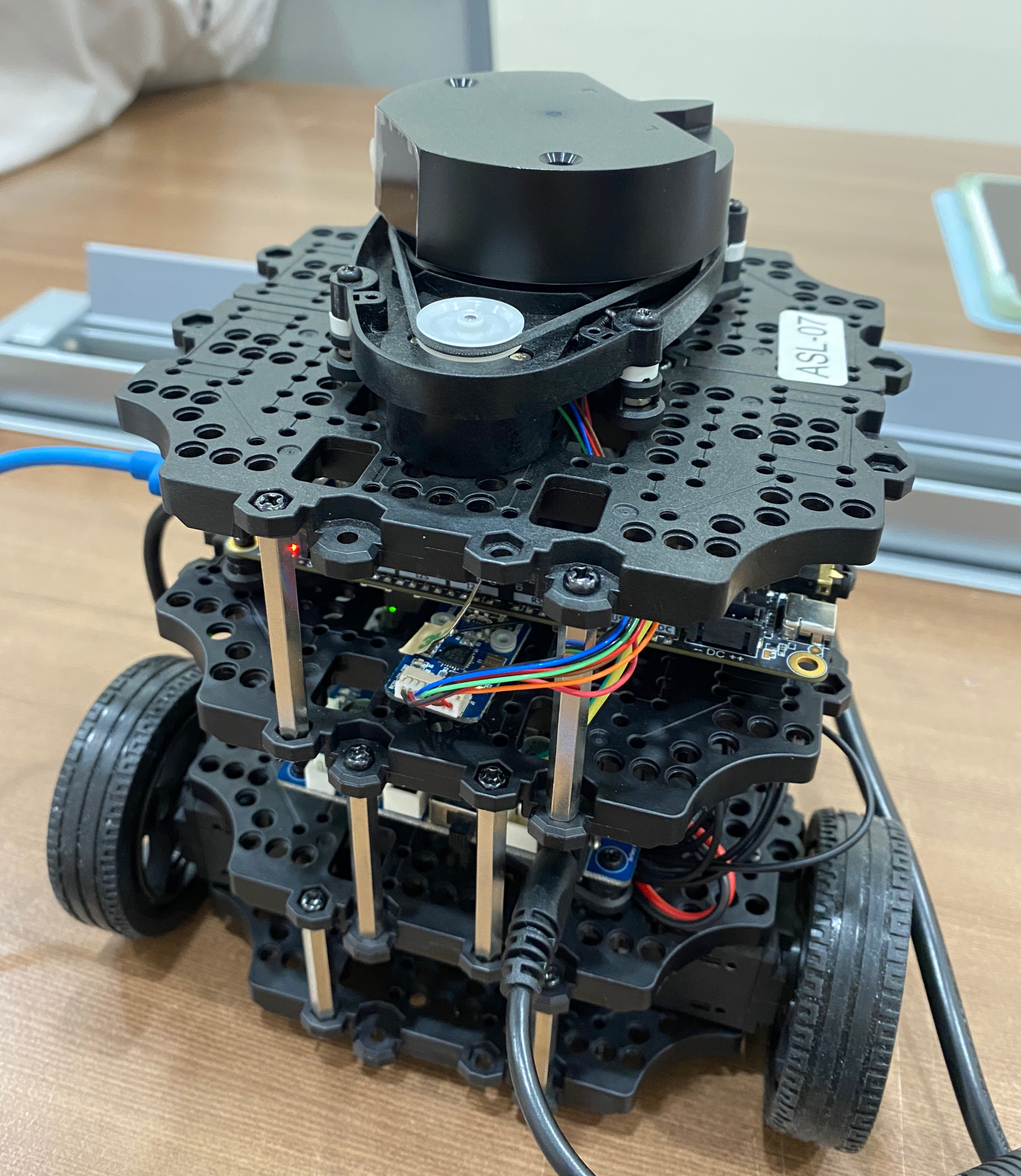
- 모바일 로봇 플랫폼: TurtleBot3 Burger
- MCU: Lattepanda
- OS: Ubuntu 18.04 LTS
- Middleware: ROS melodic
- OpenCR 1.0 사용
- remote PC: NUC
- OS: Ubuntu 18.04 LTS
- Middleware: ROS melodic
- 센서: Intel Realsense T265
First Setup
Turtlebot3 emanual
Turtlebot setup
- PC setup : Master 역할을 할 PC - Ubuntu 18.04
- SBC setup : as - ROS Melodic
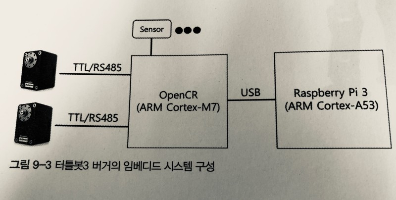
- OpenCR setup
- Open-source Control Module for ROS - 센서와 모터를 동작시키는 PC와의 중간 매개체
- OpenCR 보드를 라떼판다 보드에서 사용할 수 있도록 모듈 설치
- Bring up
- roscore 명령어를 통해 Master와 Turtlebot을 연결
roslaunch turtlebot3_bringup turtlebot3_robot.launch
slam, navigation
Slam
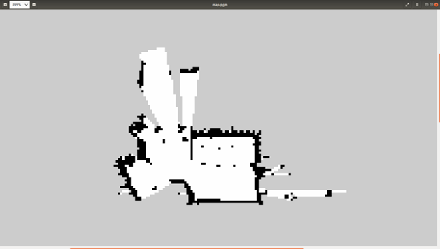
Navigation
Depth map [code]
Camera senser : Intel Realsense T265
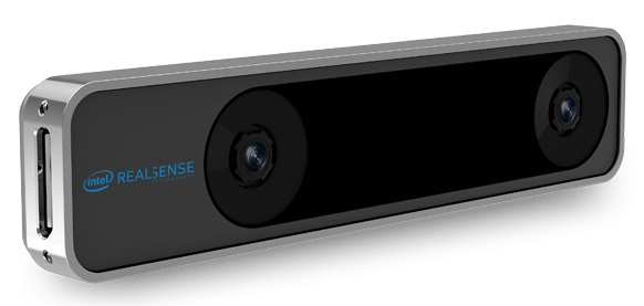
어안 렌즈 센서 2개, IMU 및 VPU 2개
Problem
- 해당 카메라는 depth map을 측정하기 위한 카메라가 아닌 현재 자신의 위치를 tracking하는데 특화된 카메라
- 일반적으로 Intel Realsense D435i 일반 렌즈 카메라와 함께 사용
하지만 우리에게 주어진 카메라는 Intel Realsense T265 하나 뿐 이였다.
왜곡된 프레임에서 depth map을 뽑아내야한다.
Node list
-
intel realsense t265 node list
/camera/accel/imu info
/camera/accel/metadata
/camera/accel/sample
/camera/fisheye1/camera info
/camera/fisheye1/image_raw
/camera/fisheye1/metadata
/camera/fisheye2/camera_info
/camera/fisheye2/image_raw
/camera/fisheye/metadata
/camera/gyro/imu_info
/camera/gyro/metadata
/camera/gyro/sample
/camera/odom/metadata
/camera /odom/sample
/camera/realsensez_camera_manager / bond
/camera/tracking_module/parameter_descriptions
/camera/tracking_module/parameter _updates
/diagnostics
/rosout
/rosout_agg
/tf /tf_static
Background
Python과 OpenCV - 46 : 스트레오 이미지로부터 깊이 맵(Depth Map) 생성하기
stereo = cv2.StereoBM_create(numDisparities=16, blockSize=15)
disparity = stereo.compute(imgL,imgR)
- OpenCV 모듈 내에 compute 함수를 사용
CV2의 이미지 표현 방식
Numpy(리스트와 유사)로 정리된 각 숫자의 크기범위 내에서 숫자가 크면 하얀색 작을수록 검은색을 칠함 각 픽셀 수만큼 이미지가 나옴 범위는 0~1이고 0.아래는 검정 1이상은 하얀색
import cv2
import numpy as np
dis = np.arange(1000000).reshape(1000,1000)
print(dis)
img = np.array(dis, dtype=np.uint8) # 여기서 변환
cv2.imshow('disparity',dis/1000000)
cv2.waitKey(0)
cv2.destroyAllWindows()
다음 코드을 보면
1000 * 1000 행렬
[[ 0 1 2 … 997 998 999] [ 1000 1001 1002 … 1997 1998 1999] [ 2000 2001 2002 … 2997 2998 2999] … [997000 997001 997002 … 997997 997998 997999] [998000 998001 998002 … 998997 998998 998999] [999000 999001 999002 … 999997 999998 999999]]
100 * 100 행렬 [[ 0 1 2 … 97 98 99] [ 100 101 102 … 197 198 199] [ 200 201 202 … 297 298 299] … [9700 9701 9702 … 9797 9798 9799] [9800 9801 9802 … 9897 9898 9899] [9900 9901 9902 … 9997 9998 9999]]
깊이 계산
disparity = stereo.compute(rect_left_image, rect_right_image).astype(np.float32)/16
계산한 값을 0~1사이로 조정
disparity = (disparity - minDisp) / numDisp
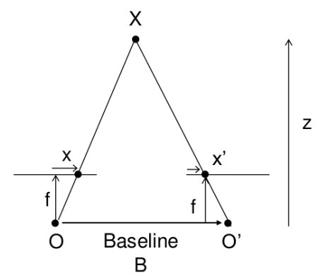
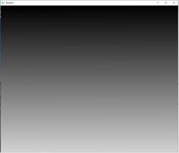
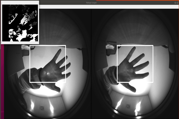
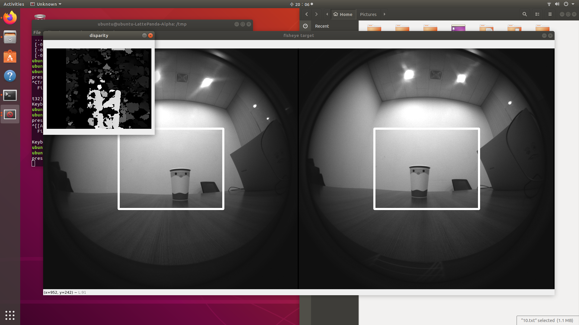
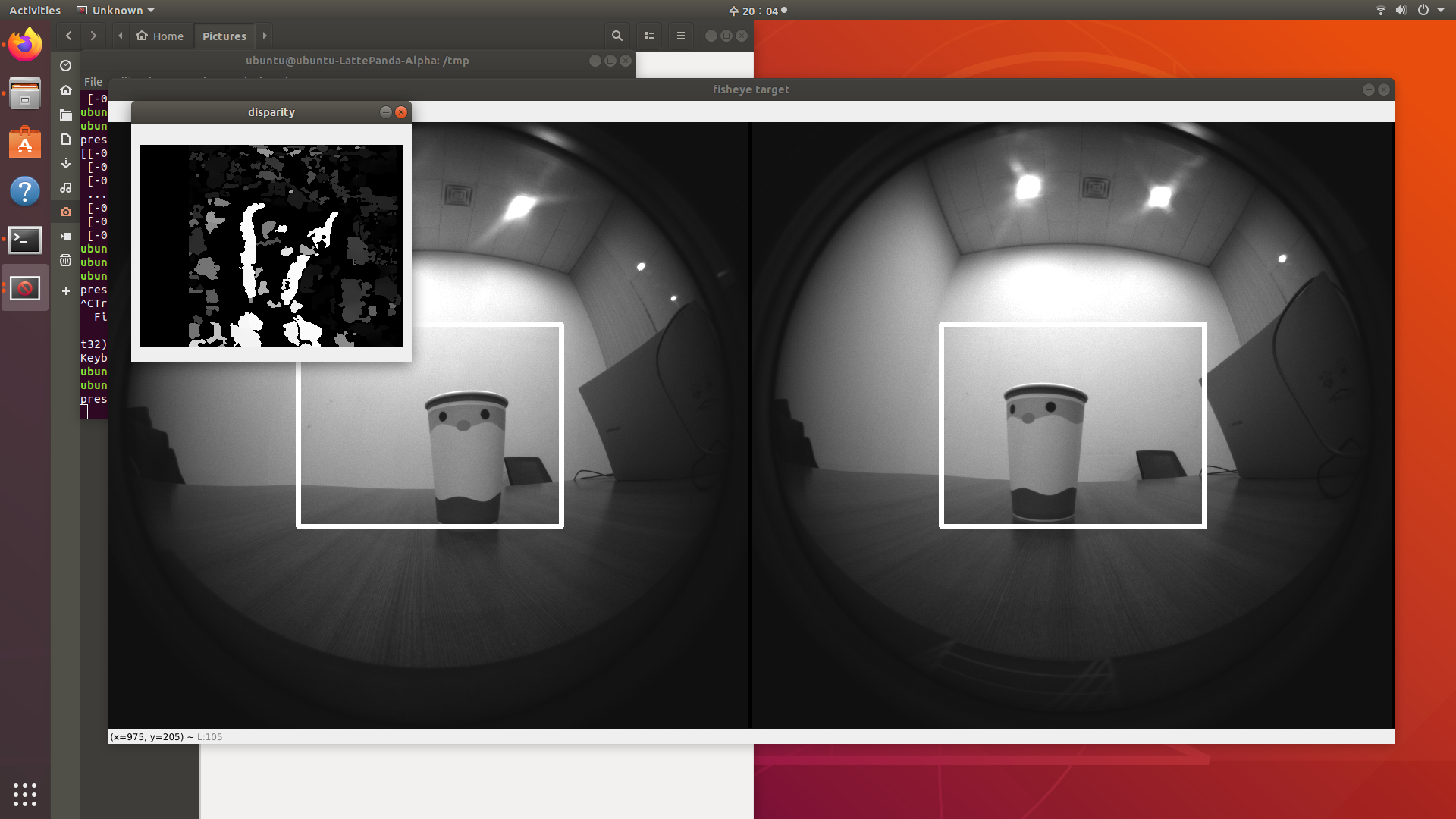
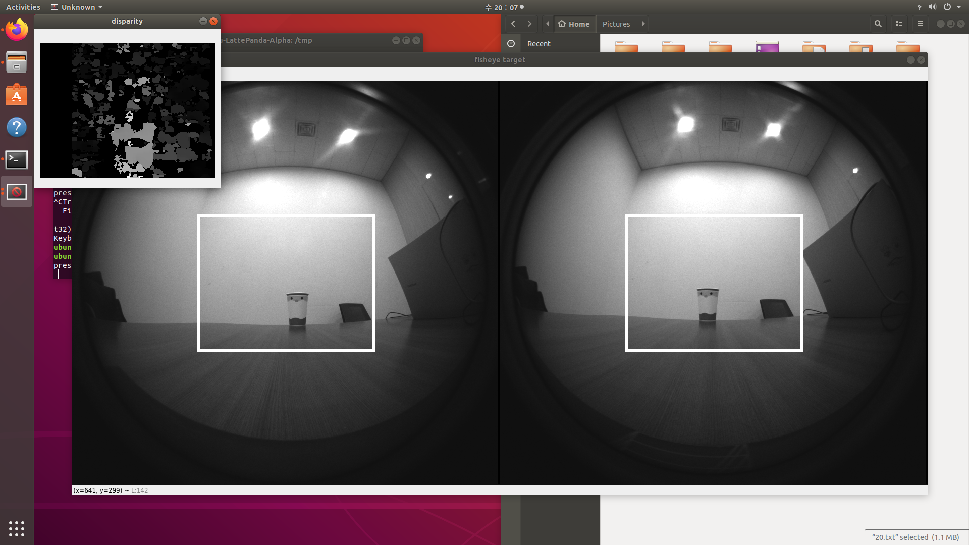
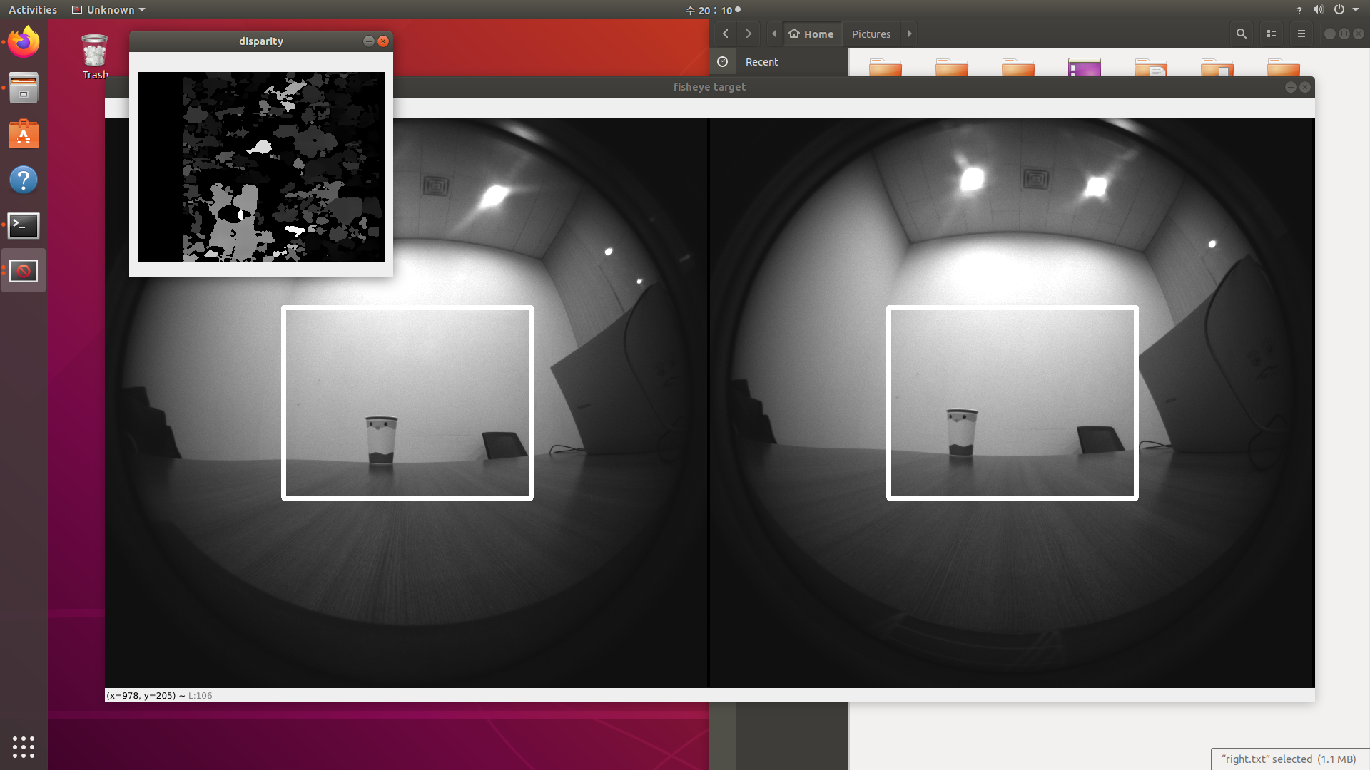
왜 disparity Map(차이 맵)의 성능은 좋지 않은가?
Disparity Map은 스테레오 비전 시스템에서 두 개의 카메라(또는 두 개의 시점)로 촬영한 이미지 간의 시차(Disparity)를 계산하여 생성된 2D 이미지
위의 사진들에서 보면 알 수 있듯이, disparity Map의 결과가 그렇게 좋은 편은 아니다. 이 이유에 대한 탐구를 진행해보았는데, 지금 작성한 코드가 단순히 픽셀간의 밝기 값 차이만 비교하는 프로그램이기 때문에 그럴 것이라는 결론을 내릴 수 있었다. 단순히 거리값만 비교하는 과정엔 많은 예외 사항이 존재한다.
고로, 더 나은 disparity Map을 얻기 위해선 픽셀 밝기 값 차이를 더 잘 비교해줄 알고리즘을 추가적으로 이용한다거나, 노이즈를 canceling 해줄 효과적인 방법을 추가적으로 도입할 필요성이 있다. 흥미가 생겨 인터넷을 탐색해보니, disparity Map의 성능을 좋게 해줄 알고리즘으로 belief propagation 등 을 사용하거나, 픽셀간의 거리 탐색에서 SAD(Sum of Absolute difference, 본 코드에서 사용한 방법) 대신 SSD(Sum of Squared difference)나 NCC 등을 사용해 밝기 차의 문제를 해결하고 있음을 새롭게 알게 되었다.
stereo camera depth data
위의 예시를 직접적으로 이용했다.
UbuntuでIntel RealSense T265を動かしてみた
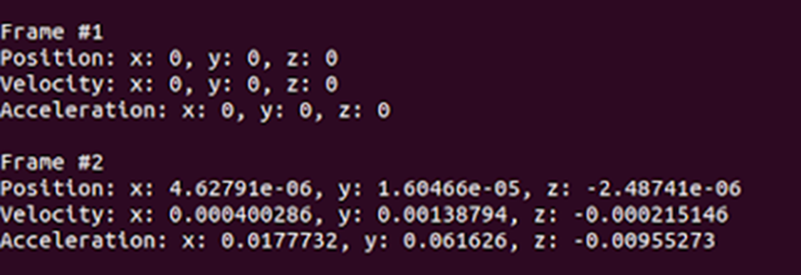
자기 위치 반환
변형한 코드
#!/usr/bin/python
# -*- coding: utf-8 -*-
# First import the library
import pyrealsense2 as rs
import numpy as np
import cv2
# setup opencv stereo
minDisp = 0
numDisp = 64 - minDisp
windowSize = 5
stereo = cv2.StereoSGBM_create(
minDisparity = minDisp,
numDisparities = numDisp,
blockSize = 16,
P1 = 8*3*windowSize**2,
P2 = 32*3*windowSize**2,
disp12MaxDiff = 1,
uniquenessRatio = 10,
speckleWindowSize = 100,
speckleRange = 32
)
# Declare RealSense pipeline, encapsulating the actual device and sensors
pipe = rs.pipeline()
# Build config object and request pose data
cfg = rs.config()
cfg.enable_stream(rs.stream.fisheye, 1)
cfg.enable_stream(rs.stream.fisheye, 2)
# Start streaming with requested config
pipe.start(cfg)
print('press q to quit this program')
try:
while True:
# Wait for the next set of frames from the camera
frames = pipe.wait_for_frames()
# Get images
# fisheye 1: left, 2: right
fisheye_left_frame = frames.get_fisheye_frame(1)
fisheye_right_frame = frames.get_fisheye_frame(2)
fisheye_left_image = np.asanyarray(fisheye_left_frame.get_data())
fisheye_right_image = np.asanyarray(fisheye_right_frame.get_data())
# Calculate disparity
width = fisheye_left_frame.get_width()
height = fisheye_left_frame.get_height()
x1 = int(width/3 - numDisp / 2)
x2 = int(width*2/3 + numDisp / 2)
y1 = int(height/3)
y2 = int(height*2/3)
rect_left_image = fisheye_left_image[y1:y2, x1:x2]
rect_right_image = fisheye_right_image[y1:y2, x1:x2]
disparity = stereo.compute(rect_left_image, rect_right_image).astype(np.float32)/16
disparity = (disparity - minDisp) / numDisp
rows, columns = disparity.shape
temp = np.ones(shape=(1, rows), dtype=np.float32)
line = (temp @ disparity).argmax()
# Display images
cv2.rectangle(fisheye_left_image, (x1, y1), (x2, y2), (255,255,255), 5)
cv2.rectangle(fisheye_right_image, (x1, y1), (x2, y2), (255,255,255), 5)
cv2.line(disparity,(line, 0), (line, rows), (255, 255, 0), thickness=10, lineType=cv2.LINE_AA)
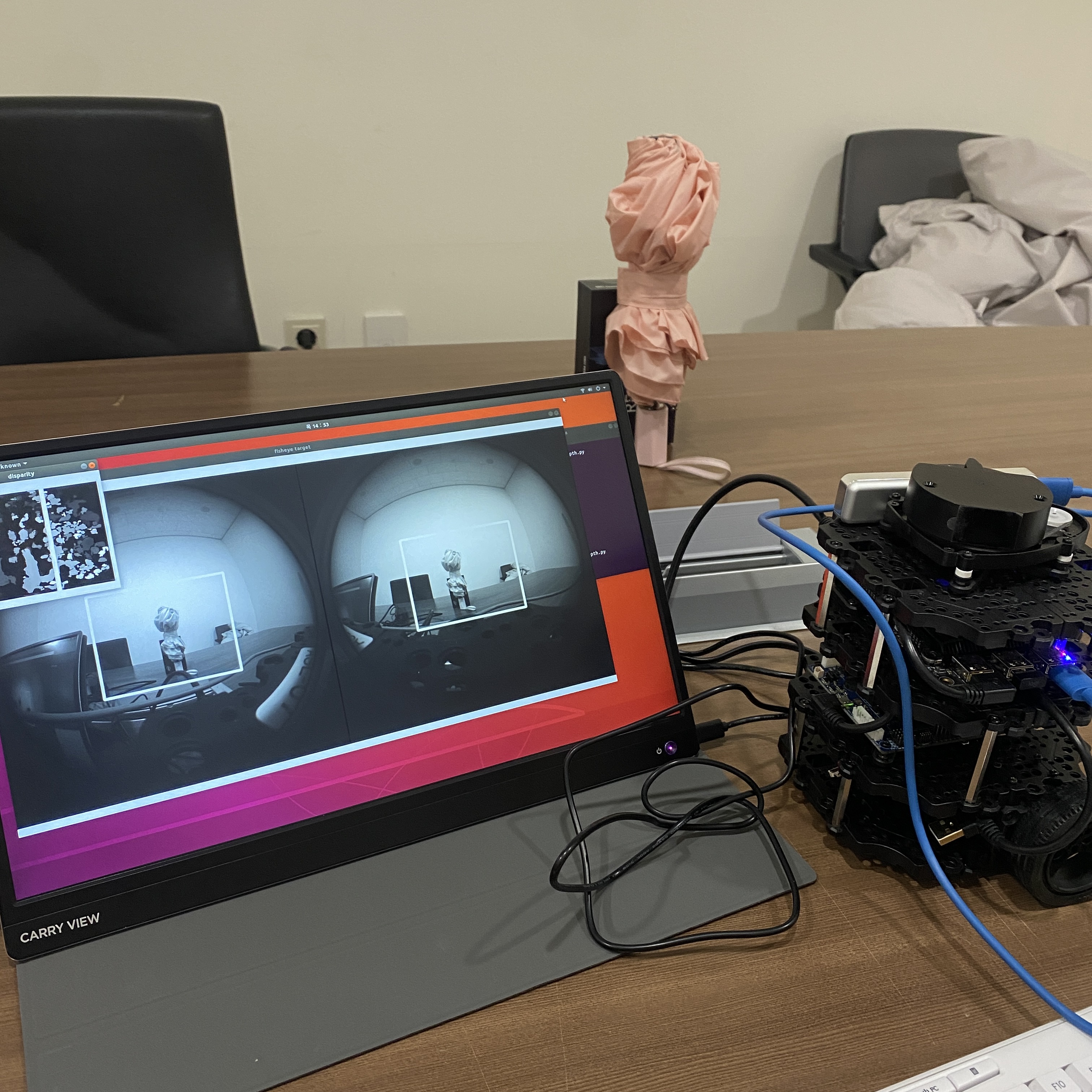
cv2.imshow('fisheye target', np.hstack((fisheye_left_image, fisheye_right_image)))
cv2.imshow('disparity', disparity)
key = cv2.waitKey(1)
if key == ord('q'):
break
finally:
pipe.stop()
Result image

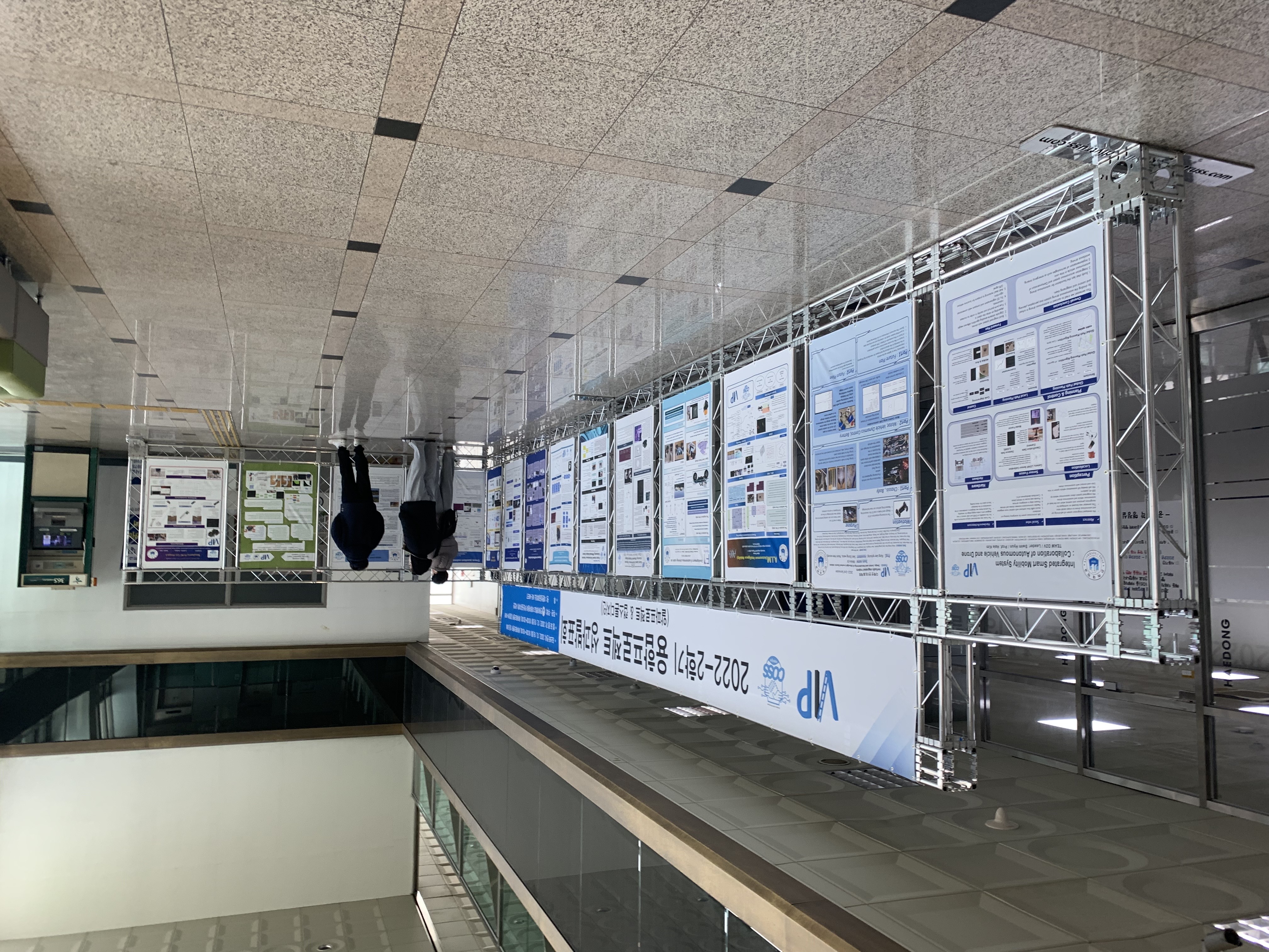
성과발표회 및 결과
인하대학교 알파프로젝트 TEAM. TurtleShip 프로젝트
2022-2학기 융합프로젝트 장려상 수상
지금 프로젝트를 다시 한다면?
왜곡을 줄여줄 수 있는 모듈을 제작 → 왜곡 현상을 보정하여 해당 문제를 해결
혹은 cv2.remap 함수를 활용 수식을 통해 해결
- 왜곡 계수 추정:
cv2.calibrateCamera를 사용해 추정. - 맵핑 좌표 생성:
cv2.initUndistortRectifyMap사용. - 이미지 보정:
cv2.remap으로 재구성.
참고자료 : https://learnopencv.com/camera-calibration-using-opencv/

1단계: 체커보드 패턴으로 실세계 좌표 정의
2단계: 다양한 시점에서 체커보드의 여러 이미지 캡처
3단계 : 체커보드의 2D 좌표 찾기 : 체커보드 코너 찾기 → 체커보드 코너 개선
4단계: 카메라 캘리브레이션
#!/usr/bin/env python

import cv2
import numpy as np
import os
import glob

# Defining the dimensions of checkerboard
CHECKERBOARD = (6,9)
criteria = (cv2.TERM_CRITERIA_EPS + cv2.TERM_CRITERIA_MAX_ITER, 30, 0.001)

# Creating vector to store vectors of 3D points for each checkerboard image
objpoints = []
# Creating vector to store vectors of 2D points for each checkerboard image
imgpoints = []


# Defining the world coordinates for 3D points
objp = np.zeros((1, CHECKERBOARD[0] * CHECKERBOARD[1], 3), np.float32)
objp[0,:,:2] = np.mgrid[0:CHECKERBOARD[0], 0:CHECKERBOARD[1]].T.reshape(-1, 2)
prev_img_shape = None

# Extracting path of individual image stored in a given directory
images = glob.glob('./images/*.jpg')
for fname in images:
    img = cv2.imread(fname)
    gray = cv2.cvtColor(img,cv2.COLOR_BGR2GRAY)
    # Find the chess board corners
    # If desired number of corners are found in the image then ret = true
    ret, corners = cv2.findChessboardCorners(gray, CHECKERBOARD, cv2.CALIB_CB_ADAPTIVE_THRESH + cv2.CALIB_CB_FAST_CHECK + cv2.CALIB_CB_NORMALIZE_IMAGE)

    """
    If desired number of corner are detected,
    we refine the pixel coordinates and display
    them on the images of checker board
    """
    if ret == True:
        objpoints.append(objp)
        # refining pixel coordinates for given 2d points.
        corners2 = cv2.cornerSubPix(gray, corners, (11,11),(-1,-1), criteria)

        imgpoints.append(corners2)

        # Draw and display the corners
        img = cv2.drawChessboardCorners(img, CHECKERBOARD, corners2, ret)

    cv2.imshow('img',img)
    cv2.waitKey(0)

cv2.destroyAllWindows()

h,w = img.shape[:2]

"""
Performing camera calibration by
passing the value of known 3D points (objpoints)
and corresponding pixel coordinates of the
detected corners (imgpoints)
"""
ret, mtx, dist, rvecs, tvecs = cv2.calibrateCamera(objpoints, imgpoints, gray.shape[::-1], None, None)

print("Camera matrix : \n")
print(mtx)
print("dist : \n")
print(dist)
print("rvecs : \n")
print(rvecs)
print("tvecs : \n")
print(tvecs)